Multi Gague - "Gauge of Eternal Coolness" :D

Update:

Things are progressing. Layout of the new circuit board design is underway. Here's a screenshot of the design with all components placed on the board:

MULTIGAUGE_COMPS_&_PADS.jpg


It's not finalized, but it's getting close.
 
The real answer is that I don't know for sure. But historically they have been sold for around $200 in the US.

We are trying to keep the cost as low as possible.
 
Some updates, folks. The PCB layout is nearly complete. I need to go over it, and do some thorough checking, and then it will be ready for fabrication and assembly. Here are some images of the single board, the fabrication panel, and a short video of what the MG looks like inside the dash.

MG_Board_Design.jpg


MG_Fab_Assy_Array.jpg


[video=youtube;789bk3mi6iI]https://www.youtube.com/watch?v=789bk3mi6iI[/video]


I don't have all the numbers in yet, but from what I have so far, it looks promising that we'll be able to keep the cost right around $200. Part of this will depend on me allowing the PCB fab to take 3-4 weeks. That makes a huge impact on what I have to pay per board, so patience will save everyone some money here. :)

For the electro-heads out there, some design info:

4 layers
370HR
.062" thick
SMOBC, then ENIG on all exposed metal
Via in pad, filled with non-conductive epoxy then plated over and planarized before final finish
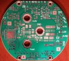
This is serious work!! Thanks man, its awesome!
 
Hey guys, sorry I haven't posted up here in a while. Yes, there has been progress. Prototype PCBs are done and in hand. I'm waiting on some of the parts to begin building up a couple of prototype assembled boards. That should happen this week. Then it will be a week or so of debug, I may need to do some updates on the board, then I'll be making a production order on the boards and PCB assembly. Figure 4-6 weeks from now.

The boards I got in look good - now I just need to make sure they work :)

Here's a pic:

prototype_PCB_small.jpg


Once I am ready for the production run, I'll be posting up here to get all the names of people who are serious about ordering. Since production costs for a bunch of them will run into several thousand $$, I'll be asking for an up-front deposit. I'm going to be fronting some of the cost myself, so I'll definitely share in that, but probably won't be able to swing all of it.

I'll be checking back on this thread to see who wants one. Anyone who has not yet expressed interest, now is the time to start planning if you want one. I don't yet have a firm price, but from all I've been able to find out so far, it will still be in the $200 range. Certainly won't grow anywhere near $300. I'm doing all I can to keep the costs down, but still make a quality unit. I like the way this thing is coming together and I think there are going to be a lot of happy FZ1 riders come summer riding season.

PM me if you have any questions, concerns, whatever.
 

Attachments

  • prototype_PCB_small.jpg
    prototype_PCB_small.jpg
    534.4 KB · Views: 80
Mechanical fit check - it works :)

I assembled the board with some of the PEM fasteners and standoffs. The standoffs I used are too long for the final design, but the simulate the position of the faceplate as it will be when the display and faceplate are installed.

Everything fits and there are no interference issues with any part of the gauge housing. There is some clearance between the mounting screws and the holes in the main gauge PCB they go through, so it should never be difficult to get it to fit.

Some pics: (note, in the final design, the board will be deeper than it is now, due to the long standoffs I used for this fit check)

mech_fit_check_02.jpg


mech_fit_check_03.jpg


mech_fit_check_04.jpg


mech_fit_check_05.jpg


mech_fit_check_06.jpg


mech_fit_check_07.jpg


mech_fit_check_08.jpg


Here is another one with the hardest part of the electronic components (the microprocessor) installed. I'll do the rest by hand in the next couple of days:

micro_assembled.jpg


It's coming together, folks. :)
 
Back
Top